INDUCTANCE
Property in an electrical circuit where a change in the electric current through that circuit induces an electromotive force (EMF) that opposes the change in current.
In electrical circuits, any electric current, i, produces a magnetic field and hence generates a total magnetic flux, Φ, acting on the circuit. This magnetic flux, due to Lenz's law, tends to act to oppose changes in the flux by generating a voltage (a back EMF) in the circuit that counters or tends to reduce the rate of change in the current.
The term 'inductance' was coined by Oliver Heaviside in February 1886.[1] It is customary to use the symbol L for inductance, possibly in honour of the physicist Heinrich Lenz.
The unit of inductance is the henry (H), named after American scientist and magnetic researcher Joseph Henry. 1 H = 1 Wb/A.
A. Mutual inductance
The mutual inductance by a filamentary circuit i on a filamentary circuit j is given by the double integral Neumann formula

The symbol μ0 denotes the magnetic constant (4π × 10−7 H/m), Ci and Cj are the curves spanned by the wires, Rij is the distance between two points. See a derivation of this equation.
B. Self-inductance
Formally the self-inductance of a wire loop would be given by the above equation with i = j. However, 1/R becomes infinite and thus the finite radius a along with the distribution of the current in the wire must be taken into account. There remain the contribution from the integral over all points where |R| ≥ a/2 and a correction term,
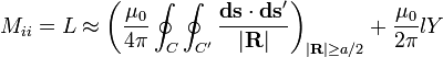
Here a and l denote radius and length of the wire, and Y is a constant that depends on the distribution of the current in the wire: Y = 0 when the current flows in the surface of the wire (skin effect), Y = 1/4 when the current is homogenuous across the wire. This approximation is accurate when the wires are long compared to their cross-sectional dimensions. Here is a derivation of this equation.
I. Inductance in Series Circuit
follow the same law, in that the total inductance of non-coupled inductors in series is equal to the sum of their individual inductances:


However, in some situations it is difficult to prevent adjacent inductors from influencing each other, as the magnetic field of one device couples with the windings of its neighbours. This influence is defined by the mutual inductance M. For example, if you have two inductors in series, there are two possible equivalent inductances depending on how the magnetic fields of both inductors influence each other.
When there are more than two inductors, the mutual inductance between each of them and the way the coils influence each other complicates the calculation. For a larger number of coils the total combined inductance is given by the sum of all mutual inductances between the various coils including the mutual inductance of each given coil with itself, which we term self-inductance or simply inductance. For three coils, there are six mutual inductances M12, M13, M23 and M21, M31 and M32. There are also the three self-inductances of the three coils: M11, M22 and M33.
Therefore
- Ltotal = (M11 + M22 + M33) + (M12 + M13 + M23) + (M21 + M31 + M32)
By reciprocity Mij = Mji so that the last two groups can be combined. The first three terms represent the sum of the self-inductances of the various coils. The formula is easily extended to any number of series coils with mutual coupling. The method can be used to find the self-inductance of large coils of wire of any cross-sectional shape by computing the sum of the mutual inductance of each turn of wire in the coil with every other turn since in such a coil all turns are in series.
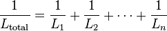
II. Inductance in Parallel Circuit
follow the same law, in that the total inductance of non-coupled inductors in parallel is equal to the reciprocal of the sum of the reciprocals of their individual inductances:

- If the inductors are situated in each other's magnetic fields, this approach is invalid due to mutual inductance. If the mutual inductance between two coils in parallel is M, the equivalent inductor is:

If L1 = L2

- The sign of M depends on how the magnetic fields influence each other. For two equal tightly coupled coils the total inductance is close to that of each single coil. If the polarity of one coil is reversed so that M is negative, then the parallel inductance is nearly zero or the combination is almost non-inductive. We are assuming in the "tightly coupled" case M is very nearly equal to L. However, if the inductances are not equal and the coils are tightly coupled there can be near short circuit conditions and high circulating currents for both positive and negative values of M, which can cause problems.
- More than 3 inductors becomes more complex and the mutual inductance of each inductor on each other inductor and their influence on each other must be considered. For three coils, there are three mutual inductances M12, M13 and M23. This is best handled by matrix methods and summing the terms of the inverse of the L matrix (3 by 3 in this case).
The pertinent equations are of the form: 
This comment has been removed by the author.
ReplyDelete