EMF EQUATION CONCEPT OF DC GENERATOR
Emf and Internal Resistance
Now, real batteries are constructed from materials which possess non-zero resistivities. It follows that real batteries are not just pure voltage sources. They also possess internal resistances. Incidentally, a pure voltage source is usually referred to as an emf (which stands for electromotive force). Of course, emf is measured in units of volts. A battery can be modeled as an emf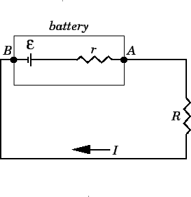
Consider the battery in the figure. The voltage ![]() of the battery is defined as the difference in electric potential between its positive and negative terminals: i.e., the points
of the battery is defined as the difference in electric potential between its positive and negative terminals: i.e., the points ![]() and
and ![]() , respectively. As we move from
, respectively. As we move from ![]() to
to ![]() , the electric potential increases by
, the electric potential increases by ![]() volts as we cross the emf, but then decreases by
volts as we cross the emf, but then decreases by ![]() volts as we cross the internal resistor. The voltage drop across the resistor follows from Ohm's law, which implies that the drop in voltage across a resistor
volts as we cross the internal resistor. The voltage drop across the resistor follows from Ohm's law, which implies that the drop in voltage across a resistor ![]() , carrying a current
, carrying a current ![]() , is
, is ![]() in the direction in which the current flows. Thus, the voltage
in the direction in which the current flows. Thus, the voltage ![]() of the battery is related to its emf
of the battery is related to its emf ![]() and internal resistance
and internal resistance ![]() via
via
| (133) |
| (134) |
 I_0$" align="MIDDLE" border="0" width="55" height="35"> the voltage
 A real battery is usually characterized in terms of its emf ![]() (i.e., its voltage at zero current), and the maximum current
(i.e., its voltage at zero current), and the maximum current ![]() which it can supply. For instance, a standard dry cell (i.e., the sort of battery used to power calculators and torches) is usually rated at
which it can supply. For instance, a standard dry cell (i.e., the sort of battery used to power calculators and torches) is usually rated at ![]() and (say)
and (say) ![]() . Thus, nothing really catastrophic is going to happen if we short-circuit a dry cell. We will run the battery down in a comparatively short space of time, but no dangerously large current is going to flow. On the other hand, a car battery is usually rated at
. Thus, nothing really catastrophic is going to happen if we short-circuit a dry cell. We will run the battery down in a comparatively short space of time, but no dangerously large current is going to flow. On the other hand, a car battery is usually rated at ![]() and something like
and something like ![]() (this is the sort of current needed to operate a starter motor). It is clear that a car battery must have a much lower internal resistance than a dry cell. It follows that if we were foolish enough to short-circuit a car battery the result would be fairly catastrophic (imagine all of the energy needed to turn over the engine of a car going into a thin wire connecting the battery terminals together).
(this is the sort of current needed to operate a starter motor). It is clear that a car battery must have a much lower internal resistance than a dry cell. It follows that if we were foolish enough to short-circuit a car battery the result would be fairly catastrophic (imagine all of the energy needed to turn over the engine of a car going into a thin wire connecting the battery terminals together).
EMF EQUATION & ARMATURE RESISTANCE
We shall now derive an expression for the e.m.f. generated in a d.c. generator.
Let
Ø= flux/pole in Wb
Z = total number of armature conductors
P = number of poles
A = number of parallel paths = 2 … for wave winding
= P … for lap winding
N = speed of armature in r.p.m.
Eg= e.m.f. of the generator = e.m.f./parallel path

Armature Resistance (Ra)
The resistance offered by the armature circuit is known as armature resistance (Ra) and includes:
(i) resistance of armature winding
(ii) resistance of brushes
The armature resistance depends upon the construction of machine. Except for small machines, its value is generally less than 1Ω.
VOLTAGE & POWER EQUATION OF DC MOTOR
DC MOTOR
V = applied voltage
Eb = back e.m.f.
Ra = armature resistance
Ia = armature current
Since back e.m.f. Eb acts in opposition to the applied voltage V, the net voltage across the armature circuit is V- Eb. The
armature current Ia is given by;
Ia = (V – Eb)/ Ra
or V = Eb + IaRa ……………………………..(i)
This is known as voltage equation of the d.c. motor.

Power Equation
If Eq.(i) above is multiplied by Ia throughout, we get,
VIa = EbIa +I2aRa
VIa= electric power supplied to armature (armature input)
EbIa = power developed by armature (armature output)
I2aRa = electric power wasted in armature (armature Cu loss)
Thus out of the armature input, a small portion (about 5%) is wasted as a I2aRa and the remaining portion EbIa is converted into mechanical power within the armature.
Condition For Maximum Power
The mechanical power developed by the motor is Pm= EbIa
Now Pm=VIa -I2aRa
Since, V and Ra are fixed, power developed by the motor depends upon armature current. For maximum power, dPm/dIa should be zero.
dPm/dIa = V – 2IaRa
or IaRa = V/2
Now, V = Eb + IaRa =Eb + V/2
therefore Eb= V/2
Hence mechanical power developed by the motor is maximum when back e.m.f. is equal to half the applied voltage.
Limitations
In practice, we never aim at achieving maximum power due to the following reasons:
(i) The armature current under this condition is very large—much excess of rated current of the machine.
(ii) Half of the input power is wasted in the armature circuit. In fact, if we take into account other losses (iron and mechanical), the efficiency will be well below 50%.
Nice tutorial .Its allso very helpful http://tonysblog.in/dc-motor-and-generator-basic-principle/
ReplyDeleteeasy way click here DC Generator EMF Equation,Terminal Voltage and Ratings
ReplyDelete